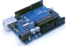
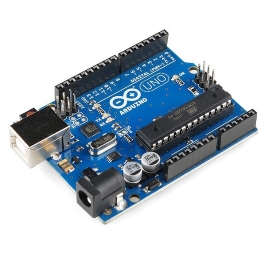
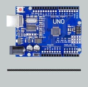
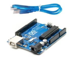
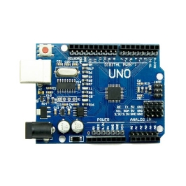
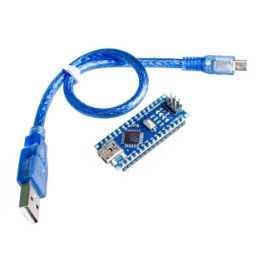
The Arduino UNO is a popular and widely used microcontroller board based on the ATmega328P chip. Developed by the Arduino company, it is part of the Arduino family of open-source hardware and software platforms designed for electronics prototyping and development. The UNO board features a simple yet powerful design, making it suitable for both beginners and advanced users alike.
One of the key features of the Arduino UNO is its versatility and ease of use. It comes with a variety of input and output pins, including digital I/O pins, analog input pins, and power pins, allowing users to interface with a wide range of sensors, actuators, and other electronic components. Additionally, the UNO board can be programmed using the Arduino Integrated Development Environment (IDE), which provides a user-friendly interface for writing, compiling, and uploading code to the board.
Another important aspect of the Arduino UNO is its open-source nature, which encourages collaboration, experimentation, and innovation within the maker community. The hardware design, schematics, and firmware of the UNO board are freely available for anyone to study, modify, and distribute, fostering a vibrant ecosystem of projects and applications. Whether used for educational purposes, hobbyist projects, or professional prototyping, the Arduino UNO continues to be a versatile and accessible platform for electronics enthusiasts around the world.
The Arduino UNO Microcontroller is a highly versatile and widely used development board based on the ATmega328P microcontroller chip. Developed by Arduino, it serves as the cornerstone of many electronics projects due to its simplicity, affordability, and extensive community support.
At its core, the Arduino UNO features a powerful 8-bit AVR microcontroller clocked at 16 MHz, providing ample processing power for a wide range of tasks. It boasts 32 KB of Flash memory for storing program code, 2 KB of SRAM for variables and runtime data storage, and 1 KB of EEPROM for non-volatile data storage.
In terms of connectivity, the Arduino UNO offers a plethora of I/O pins, including 14 digital pins (of which 6 can be used as PWM outputs), 6 analog input pins, and a variety of power pins. These pins enable users to interface with sensors, actuators, displays, and other electronic components seamlessly.
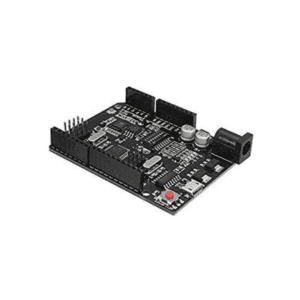
Moreover, the Arduino UNO is equipped with a USB interface, allowing for easy programming and communication with a computer. It can be programmed using the Arduino Integrated Development Environment (IDE), which provides a beginner-friendly platform for writing, compiling, and uploading code to the board.
Overall, the Arduino UNO Microcontroller is renowned for its versatility, accessibility, and robustness, making it an ideal choice for hobbyists, educators, and professionals alike seeking to bring their electronic projects to life.
Features Of Arduino UNO
The Arduino UNO Microcontroller is packed with features that make it an ideal choice for a wide range of electronics projects. Here are the key features in detail:
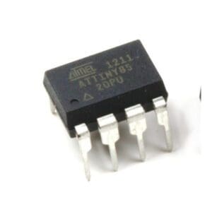
ATmega328P Microcontroller: At the heart of the Arduino UNO is the ATmega328P microcontroller, an 8-bit AVR chip manufactured by Atmel (now Microchip Technology). This microcontroller operates at 16 MHz clock speed and has 32 KB of Flash memory, 2 KB of SRAM, and 1 KB of EEPROM, providing sufficient resources for various applications.
Digital I/O Pins: The Arduino UNO comes with 14 digital I/O pins, labeled from 0 to 13. These pins can be configured as either inputs or outputs, allowing the board to interface with digital sensors, actuators, LEDs, and other components. Additionally, 6 of these pins (marked with ‘~’) support Pulse Width Modulation (PWM) for analog output.
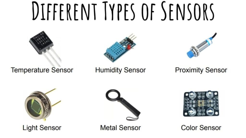
Analog Input Pins: In addition to digital I/O pins, the Arduino UNO features 6 analog input pins labeled A0 through A5. These pins can be used to read analog voltage levels from sensors such as potentiometers, temperature sensors, and light sensors, providing analog-to-digital conversion (ADC) capabilities.
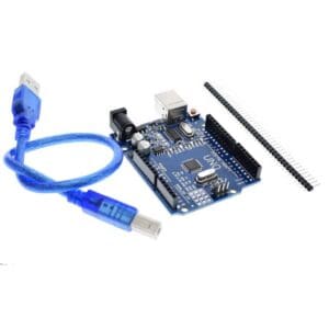
USB Interface: The Arduino UNO includes a built-in USB interface, which allows it to connect to a computer for programming and serial communication. The USB interface is used to upload sketches (programs) to the board, as well as for debugging and serial data exchange between the board and the computer.
Power Supply: The Arduino UNO can be powered via USB connection or an external power source. It supports a wide range of input voltages (7-12V), making it compatible with various power supplies, batteries, and renewable energy sources. Additionally, the board features a voltage regulator that ensures stable 5V output for powering external components.
Reset Button: The Arduino UNO includes a reset button, which allows users to restart the microcontroller and begin program execution from the beginning. This button is useful for troubleshooting and debugging purposes, as well as for initiating program uploads via the Arduino IDE.
LED Indicators: The Arduino UNO features built-in LED indicators for power (green) and pin 13 (usually connected to an onboard LED). These indicators provide visual feedback on the board’s status, helping users diagnose issues and monitor program execution.
Overall, the Arduino UNO’s rich feature set, combined with its user-friendly interface and extensive community support, makes it an excellent choice for electronics enthusiasts, educators, and professionals looking to prototype, experiment, and innovate in the field of embedded systems and IoT.
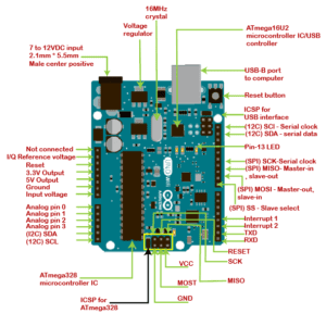
Arduino UNO Pin Discription:
The Arduino UNO features a variety of pins, each with specific functionalities. Here’s a brief description of each type of pin on the Arduino UNO:
Digital Pins (0-13):
These pins can be configured as either inputs or outputs.
They can read digital signals (HIGH or LOW) or output digital signals.
Pins 3, 5, 6, 9, 10, and 11 support Pulse Width Modulation (PWM) for analog output.
Analog Input Pins (A0-A5):
These pins are used to read analog voltage levels.
They provide analog-to-digital conversion (ADC) functionality.
Each pin can measure a voltage between 0 and 5 volts.
Power Pins:
5V: Provides a regulated 5-volt supply for powering external components.
3V: Provides a regulated 3.3-volt supply.
GND (Ground): Used as the common ground reference for the circuit.
Reset Pin (RESET):
This pin is used to reset the microcontroller.
Pulling this pin LOW resets the microcontroller and restarts the program.
Serial Communication Pins (RX, TX):
RX (Receive) and TX (Transmit) pins are used for serial communication with other devices.
They are connected to the microcontroller’s UART (Universal Asynchronous Receiver/Transmitter) for serial communication.
I2C Pins (SDA, SCL):
SDA (Serial Data) and SCL (Serial Clock) pins are used for I2C (Inter-Integrated Circuit) communication.
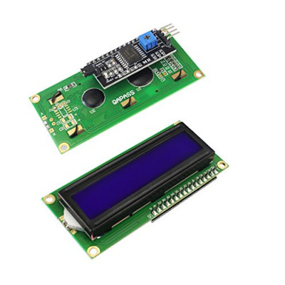
They enable communication with I2C-compatible sensors, displays, and other devices.
SPI Pins (MOSI, MISO, SCK):
MOSI (Master Out Slave In), MISO (Master In Slave Out), and SCK (Serial Clock) pins are used for SPI (Serial Peripheral Interface) communication.
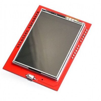
They facilitate high-speed communication with SPI-compatible devices such as SD cards, EEPROMs, and displays.
Understanding the pin descriptions of the Arduino UNO is essential for effectively interfacing with external components and designing electronic circuits.
Programming the Arduino UNO
Programming the Arduino UNO involves writing code in the Arduino programming language, which is based on C and C++. Here’s a general description of the steps involved in programming the Arduino UNO:
Setup:
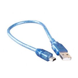
Connect the Arduino UNO to your computer using a USB cable.
Launch the Arduino IDE (Integrated Development Environment) on your computer.
Write Code:
In the Arduino IDE, start a new sketch (program) by selecting File > New.
Write your code in the editor window. The code consists of two main functions: setup() and loop().
The setup() function is executed once when the Arduino UNO is powered on or reset. It is used to initialize variables, configure pins, and perform other setup tasks.
The loop() function is executed repeatedly as long as the Arduino UNO is powered on. It is used to implement the main program logic, which typically involves reading sensors, processing data, and controlling actuators.
Upload Code:
Once you’ve written your code, verify it by clicking the Verify button (checkmark icon) in the Arduino IDE. This will compile the code and check for syntax errors.
If there are no errors, click the Upload button (right arrow icon) to upload the code to the Arduino UNO. This will compile the code again and transfer it to the microcontroller on the Arduino UNO board.
Monitor Serial Output (Optional):
You can use the Serial Monitor feature in the Arduino IDE to monitor the output of your program in real-time.
To use the Serial Monitor, add Serial.begin(baudrate) in the setup() function to initialize serial communication, and use Serial.print() or Serial.println() statements in your code to print messages or data to the serial port.
Open the Serial Monitor by clicking the magnifying glass icon in the Arduino IDE.
Debugging and Iteration:
Test your program on the Arduino UNO to ensure it behaves as expected.
If you encounter any issues or bugs, use the Serial Monitor and other debugging techniques to diagnose and fix them.
Make any necessary modifications to your code and repeat the process until your program functions correctly.
Power Off and Disconnect:
Once you’re finished programming and testing, disconnect the Arduino UNO from your computer and power it off if necessary.
By following these steps, you can effectively program the Arduino UNO to perform a wide range of tasks, from reading sensors and controlling actuators to implementing complex algorithms and logic.
Using the Arduino UNO involves several steps to set up and program the board for various applications. Here’s a general guide on how to use the Arduino UNO:
Gather Materials:
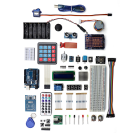
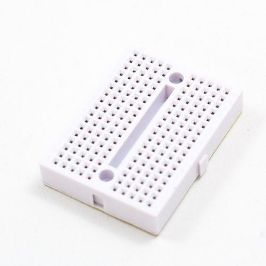
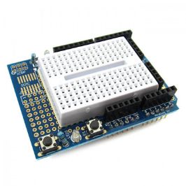
Obtain an Arduino UNO board, a USB cable, and any additional components (sensors, LEDs, resistors, etc.) needed for your project.
Install Arduino IDE:
Download and install the Arduino IDE (Integrated Development Environment) on your computer from the official Arduino website (https://www.arduino.cc/en/software).
Launch the Arduino IDE after installation.
Connect Arduino UNO:
Use a USB cable to connect the Arduino UNO board to your computer.
Ensure that the board is properly connected and powered on.
Select Board and Port:
In the Arduino IDE, select the appropriate board model (Arduino UNO) from the Tools > Board menu.
Select the serial port to which the Arduino UNO is connected from the Tools > Port menu.
Write Code:
Write your Arduino sketch (program) in the Arduino IDE. The sketch typically consists of two functions: setup() and loop().
In the setup() function, initialize variables, configure pins, and perform other setup tasks.
In the loop() function, implement the main program logic, which is executed repeatedly.
Verify and Upload Code:
Verify your code by clicking the Verify button (checkmark icon) in the Arduino IDE. This compiles the code and checks for errors.
If there are no errors, upload the code to the Arduino UNO by clicking the Upload button (right arrow icon).
The Arduino IDE will compile the code again and transfer it to the Arduino UNO board. The onboard LED (usually connected to pin 13) will blink rapidly during the upload process.
Monitor Serial Output (Optional):
If your sketch includes serial communication, you can monitor the serial output using the Serial Monitor feature in the Arduino IDE.
Open the Serial Monitor by clicking the magnifying glass icon in the Arduino IDE after uploading your sketch.
Test and Iterate:
Test your program on the Arduino UNO to ensure it behaves as expected.
If necessary, make adjustments to your code and repeat the process until your project functions correctly.
Disconnect and Power Off:
Once you’re finished using the Arduino UNO, disconnect it from your computer and power it off if necessary.
By following these steps, you can effectively use the Arduino UNO to develop and deploy a wide range of projects and applications, from simple LED blinking to more complex sensor interfacing and data logging.
Conclusion:
In conclusion, the Arduino piggy bank smart saving system represents a significant advancement in the realm of personal finance management. By combining innovative technology with the traditional concept of saving, this system offers users a practical and interactive way to cultivate healthy saving habits. Moreover, the system’s real-time tracking capabilities and visual feedback mechanisms provide users with valuable insights into their saving progress, empowering them to make informed financial decisions and work towards their goals with confidence.
Furthermore, the Arduino piggy bank smart saving system has the potential to instill lifelong financial literacy skills in users of all ages. As a result, individuals who engage with this system are likely to develop a deeper understanding of the importance of saving and budgeting, setting them on a path towards financial security and stability. Additionally, by fostering a sense of responsibility and accountability, this system encourages users to take ownership of their financial futures, ultimately leading to greater financial well-being and success.