
Automatic Door Bell Ringer Using IR Sensor and 555 Timer
The Automatic Door Bell Ringer is a smart electronic circuit that detects human presence and rings a buzzer automatically—without any manual button press. As soon as a person approaches the door, the system recognizes their presence using an IR sensor and triggers the bell through a timer IC.
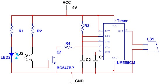
This setup uses an IR LED and a phototransistor placed side by side. Under normal conditions, the phototransistor remains inactive because it receives no reflected light. Consequently, the circuit stays off and the buzzer remains silent.
However, when someone stands near the door, the IR light reflects off their body and reaches the phototransistor. This reflection causes the phototransistor to conduct. As a result, a connected NPN transistor also activates and pulls down the trigger pin (pin 2) of the 555 timer.
Once the timer receives this LOW signal, it outputs a HIGH pulse. This pulse immediately activates the buzzer, which rings for a specific duration, indicating someone is at the door.
Overall, this project offers an affordable and reliable method to automate doorbell ringing. It improves convenience, especially in homes where hands-free operation is desired. Furthermore, the simplicity of this design makes it suitable for DIY electronics enthusiasts and basic automation setups.
Components Required
-
IR LED – emits infrared light
-
Phototransistor (NPN) – receives reflected IR light
-
BC547BP Transistor – amplifies the signal
-
555 Timer IC – configured in monostable mode to generate output pulse
-
Resistors – R1: 470Ω, R2: 100kΩ, R3 & R4: 10kΩ
-
Capacitors – C1: 0.01μF, C2: 470μF
-
Buzzer (200Hz) – for audio alert
-
9V Battery / Power Supply – Vcc
-
Breadboard, wires – circuit assembly
Circuit Connection
-
IR LED and phototransistor are placed side-by-side to form the sensor.
-
The output from the phototransistor is fed to the base of a BC547BP NPN transistor through resistor R4.
-
The transistor’s output goes to pin 2 (TRIG) of the 555 Timer IC.
-
Timer pins are configured for monostable mode, where a single pulse is triggered when the input goes LOW.
-
The buzzer is connected to pin 3 (OUT) of the timer.
-
Pin 8 of the timer is connected to 9V Vcc, while the IR sensor receives 5V.
Circuit Operation
-
Idle State:
In the absence of motion, the phototransistor receives no IR light (since it’s not being reflected), so it doesn’t conduct. As a result, the transistor remains OFF, and the timer doesn’t trigger. The buzzer stays silent. -
Person Detected:
When someone approaches, IR light from the LED reflects off them and is picked up by the phototransistor. This causes it to conduct, turning ON the BC547 transistor. -
Triggering the Timer:
The conducting transistor pulls pin 2 of the 555 timer LOW, triggering it. The timer outputs a HIGH pulse (9V) for a specific time, which activates the buzzer. -
Buzzer Rings:
The buzzer rings for the duration of the timer pulse and stops automatically—creating a touchless, automatic doorbell experience.
To Learn More Visit our Website
For more information:-www.mifraelectronics.com
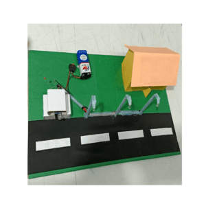
* Product Images are shown for illustrative purposes only and may differ from actual product.


Reviews
There are no reviews yet.