Electronic circuits are the backbone of modern technology, powering everything from smartphones to spacecraft. Understanding how these circuits work often involves interpreting electronic schematics and circuit diagrams. One key skill in this process is recognizing and deciphering the various symbols used to represent different electronic components. In this blog, we’ll explore the most common electronic symbols and provide insights into how they are used in schematics and diagrams.
Resistors (R):
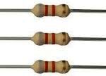
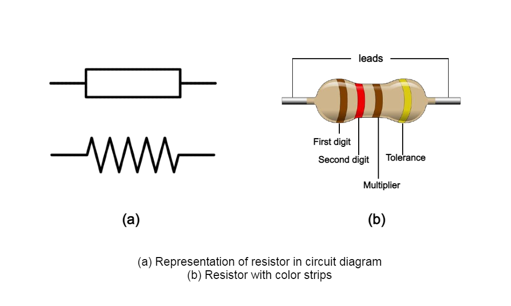
The resistor is a fundamental component in electronics, limiting the flow of electrical current. In schematics, resistors are represented by a zigzag line. The value of the resistance is usually indicated next to the symbol. Understanding resistor values is crucial for calculating voltage and current in a circuit.
Capacitors (C):
Capacitors store and release electrical energy. They are depicted as two parallel plates with a space between them. The symbol may also include arrows to indicate a variable capacitor. Capacitor values are measured in farads (F) and are specified in the schematic.
Inductors (L):
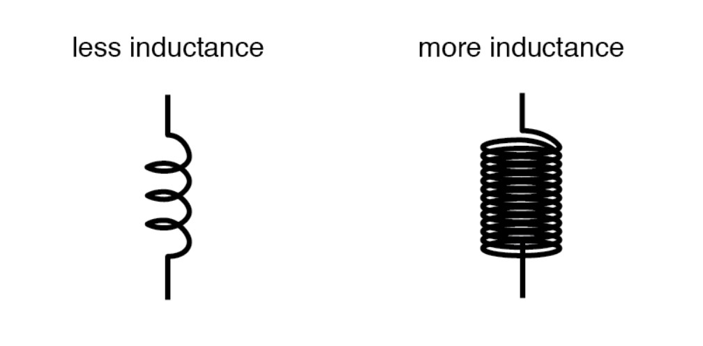
Inductors resist changes in current and are symbolized by a series of coils. The number of coils and the shape of the symbol may vary depending on the type of inductor. Inductance is measured in henrys (H), and the value is denoted on the schematic.
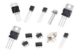
Transistors (Q):
Transistors are semiconductor devices with various applications, such as amplification and switching. Schematics represent transistors with different symbols based on their types (NPN or PNP). Understanding transistor symbols is essential for designing and troubleshooting electronic circuits.
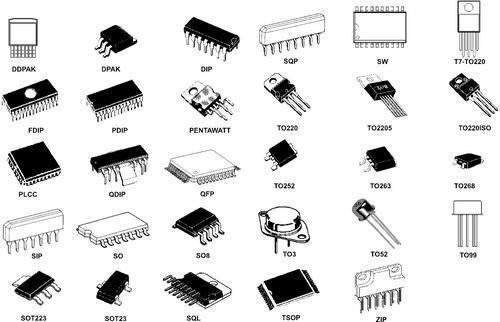
Integrated Circuits (IC):
Integrated circuits combine multiple electronic components in a single package. Their symbols are diverse and can be complex, representing the internal structure of the IC. Common elements include squares, circles, and triangles to denote different functions within the IC.
Diodes (D):
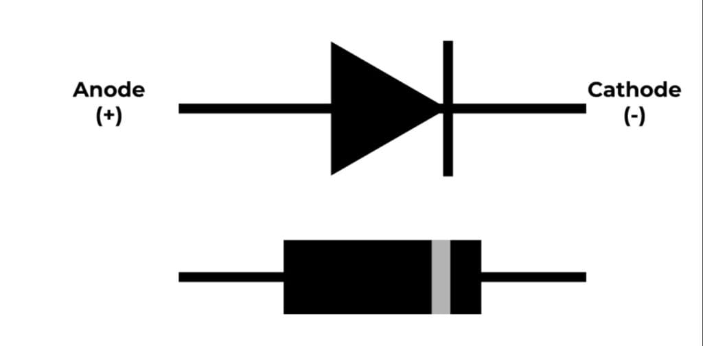
Diodes allow current to flow in one direction only. The symbol resembles an arrow pointing in the direction of allowable current flow. Understanding diodes is crucial for grasping rectification and semiconductor behavior in electronic circuits.
Deciphering electronic schematics and circuit diagrams is a valuable skill for anyone involved in electronics. This blog has provided an overview of common electronic symbols, touching on resistors, capacitors, inductors, diodes, transistors, integrated circuits, and ground symbols. By understanding these symbols, you’ll be better equipped to analyze and design electronic circuits, paving the way for innovation in the ever-evolving world of electronics.